Die automation system

The Marveloc-CURTAIN systems of Hammer-IMS can be applied in automated extrusion die control situations. Automatically controlling the gap of the extrusion die helps getting reproducible product quality, minimizes set-up times and avoids human errors reflecting in the quality of the extruded film, sheet or foam.

It should be stressed that, as a rule of thumb, feedback would only be economically viable for production batches spanning more than one worker shift. For plastic extrusion this means that production would exceed multiple tens of tons per batch. You might first have to optimize some internal operations enabling these bigger production batches before you would go for a fully-automated extrusion die.

Hammer-IMS offers complete turnkey solutions by means of the following sub-modules:


Connectivity 3.0 Extrusion Feedback Module

Connectivity 3.0 Extrusion Feedback Module on our HMI system, i.e. our feedback-capable software environment on an industrial panel pc.

A PLC-based I/O system

featuring:

  • 24V PWM signaling bus to power electronics modules for individual bolt control. For each tuning bolt, a separate 24V signal will be foreseen. Alternatively, one field-bus output to control die adjustment robots.
  • Analog or field-bus based line speed and pump flow monitoring. We will read-out the customer’s extrusion line two most important parameters. We can implement any commercially available field-bus here, though we prefer PROFINET.
  • Direct communication to our Marveloc-CURTAIN scanner systems by means of Modbus.
  • The PLC source code is made available to the skilled customer.
Power-electronics infrastructure

Power-electronics infrastructure for bolt heating when working with thermobolts. We use a solid state relay-based (thyristor) topology for maximum lifetime. Circuit drawings are made available to enable the skilled customer performing lifetime management for the installation. As an alternative to Hammer-IMS’s power-electronics infrastructure, Hammer-IMS can use the already available power-electronics infrastructure at the customer’s facilities.

An overview on a typical system is provided in the figure. The following components can be identified from left to right: panel PC HMI, industrial cabinet containing the PLC-based I/O system and power electronics infrastructure, Marveloc-CURTAIN scanner. Hammer-IMS assumes the die has already been equipped by the right adjustment technology. This is either a die adjustment robot or a set of thermobolts including global cooling mechanism.

Connectivity 3.0 and its Extrusion Feedback Module

Since operators and quality engineers will work with the panel PC and its Connectivity 3.0’s Extrusion Feedback Module, we will introduce the relevant features here. We will not give you a detailed introduction to our Connectivity 3.0 software environment here. Instead, we recommend you to read the relevant web page in case there would be any need for.

The quality of your product is always visualized on the main window of the Connectivity 3.0 software environment, with values for each active bolt. A typical graph is displayed below, showing thickness values for each bolt.

The Extrusion Feedback module is kept as simple as possible. Yet, all relevant features are in place. It consists of one window with three different tabs: machine status, controller settings and die mapping settings, respectively labeled ‘Status’, ‘Controller’ and ‘Die mapping’.

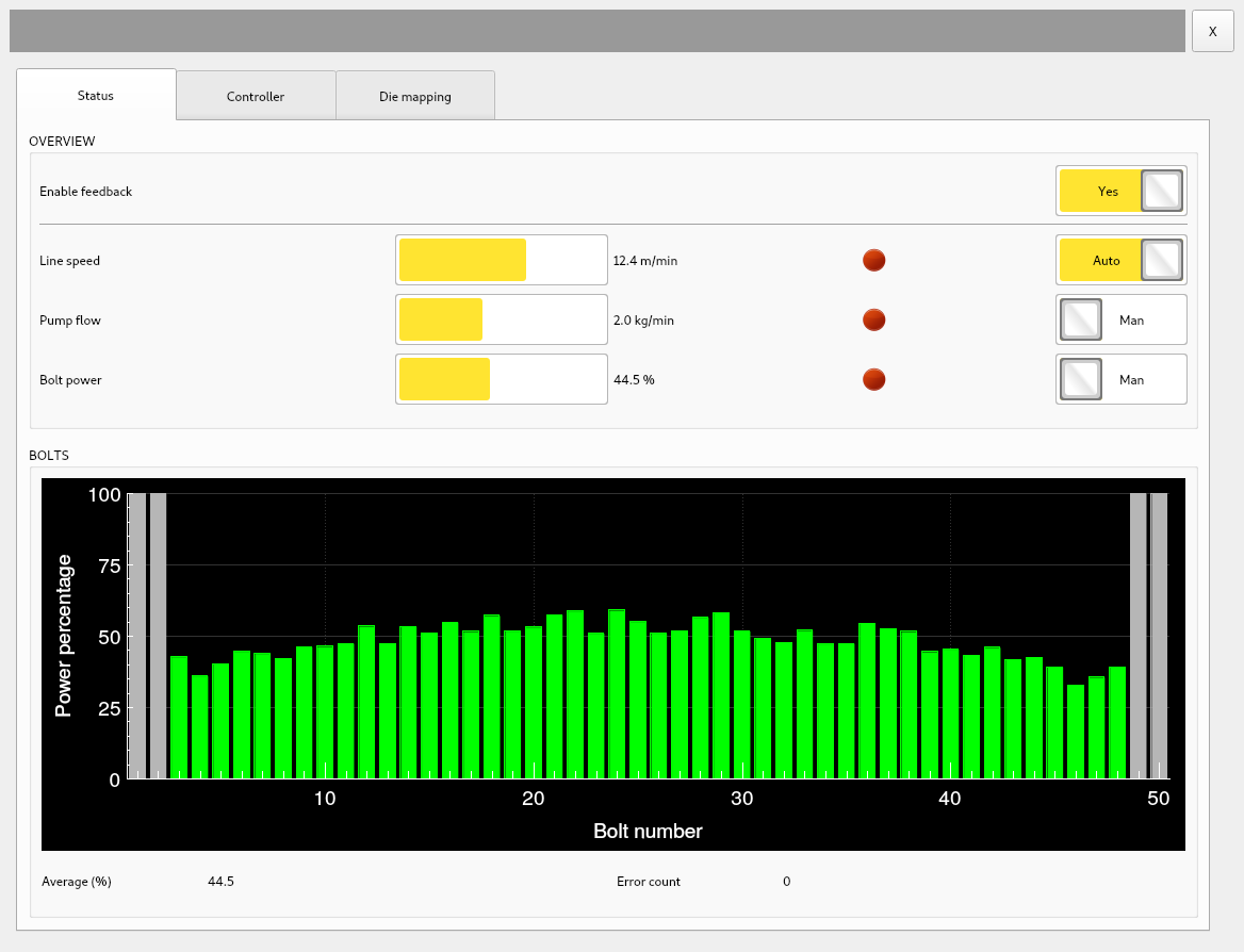
The Status-tab gives a visual overview on the actual line speed, actual pump flow and average bolt power as a percentage with respect to its maximum (typically 100-200 Watts). For optimal production and compensation headroom these values should always be mid-range. Note that automatic feedback can be toggled on and off by means of the master switch in the top right of the tab. The main menu of Connectivity 3.0 clearly displays the status of the feedback controller in a simple control light in Connectivity’s main toolbar. Green means on, red means off.

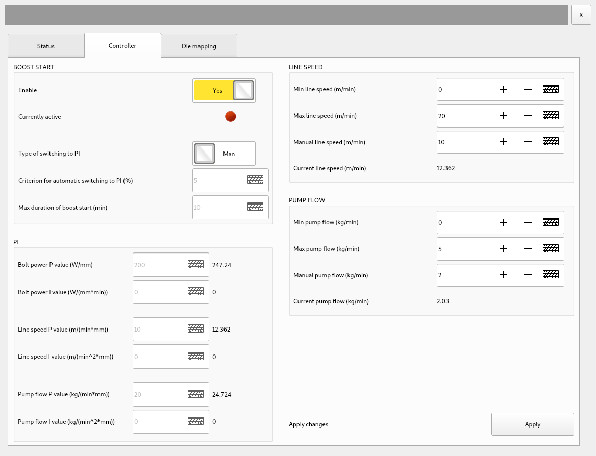
The system works with three control loops, which can each be switched on an off by an associated switch button: line speed controller, pump flow controller and bolt power controller. The first two control loops cannot be switched on simultaneously. The module controls the average profile by either intervening with the line speed or alternatively the pump flow. Controlling through the latter has the advantage that production turnovers are constant over time. The two mechanisms thus work in an exclusive fashion, meaning, when the module intervenes with the line speed setting, the pump flow will be set to a default value. Alternatively, when the module intervenes with the pump flow, the line speed will be based on a default value. The two switches next to the line speed and pump flow values therefore only work exclusively. Hammer-IMS can disable one of these permanently in case the customer only prefers to use one of the aforementioned mechanisms in all cases.

The bar chart gives a quick overview on the power of each individual bolt. Powers should be all mid-range in a normal working condition. Local highs and lows can represent defective bolts, defective heaters or die contaminations, so it is good to regularly keep an eye on this chart. Grey-marked bars on the sides (here 4 in total) represent trimmed bolts in case a narrow sheet is produced in a wider die. Output power of trimmed bolts will always be zero. Alternatively, trimming bolts can be valuable in case the customer does not want the material edges to be controlled by the automated feedback.

The second tab shows all the control parameters of interest for a fully-automated die as well as two important switches related to production start-up. A screenshot is provided on the left. Editing the parameters is generally only possible by the customer’s in-house control expert after having introduced a 4-digit password. Operators are not supposed to intervene here. Note that switches do remain accessible for operators. There is a boost-start function in the top left. This boost-start function enables quick machine settling at the beginning of a production batch. It is basically an open-loop controller outputting the standard product’s recipe values to pump flow and line speed while setting output powers of each bolt to 50%. The boost-start function can shutdown itself when the thickness profile is within an acceptable tolerance level. This option is enabled when the ‘Type of swithing to PI’ switch shows ‘Auto’. The tolerance level is set through the input ‘Criterion for automatic switching to PI (%)’.

The tab also enables editing the PI-controllers’ fixed feedback parameters for all three installed control loops: bolt power control, line speed control and pump flow control. Note that the latter two cannot work simultaneously as already discussed above. These so-called fixed feedback parameters are used together with the machine state to derive the actual PI parameters, which are in charge in the controller and displayed next to the input fields.

The sections ‘line speed’ and ‘pump flow’ specify a working range in which the controller is allowed to ‘wander’ when controlling the process. Manual line speed and pump flow values can be specified. Current values are repeated here for ease of use.

Most of these parameters are considered not to differ over the product range of the customer. Nevertheless, some of them can be linked to the product’s recipe which means the correct value is automatically put in place whenever the extrusion equipment is prepared for your next product.

The last tab enables the advanced user to choose and configure the bolt mapping algorithm. This is basically the piece of software mapping the scanner’s measured thickness data to the actual thermobolt which needs a tune. Four mapping algorithms are available: linear mapping, smoothened non-linear mapping, piece-wise non-linear mapping or true non-linear mapping. All four can be parameterized accordingly.

Undoing bolt cross-sensitivity or compensating influence of neighboring bolts can be done by a weighted neighbor-based linear FIR filter, which can be parameterized in the tab as well.

Last, a feature called randomization can contribute to an even better extrusion product. This feature can be installed on request in our Extrusion Feedback Module and is not shown in the screenshot on the right.